What is a VLAN Network?
Types of VLANs Explained
In short, there are 2 types of VLANs:
- Port-based VLANs (untagged)
- Tagged VLANs
Port-based VLANs

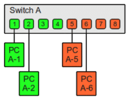
Eight-port switch with two port-based VLANs
Source: https://www.thomas-krenn.com/en/wiki/VLAN_Basics
| Switch A | ||
| Switch-Port | VLAN ID | Connected device |
| 1 | 1(green) | PC A-1 |
| 2 | PC A-2 | |
| 3 | (not used) | |
| 4 | (not used) | |
| 5 | 2(orange) | PC A-5 |
| 6 | PC A-6 | |
| 7 | (not used) | |
| 8 | (not used) | |
With the switches and VLANs set up this way, all of the PCs have been connected to one physical switch, only the following PCs can communicate with each other due to the configuration of the VLAN:
- PC A-1 with PC A-2 -VLAN 1 – Green
- PC A-5 with PC A-6 – VLAN 2 – Orange
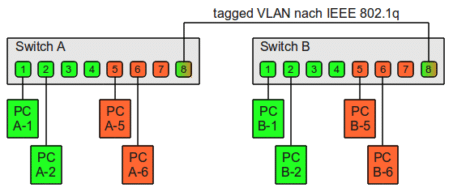
To extend this example, assume that there are also four PCs in the neighboring room that PC A-1 and PC A-2 should be able to communicate with called PC B-1 and PC B-2. Communication between PC B-5 and PC B-6 in Room 2 and PC A-5 and PC A-6 in room one is required while preventing A1-2 & B1-2 (Green) from communication with A5-6 & B5-6 (Orange) or the reverse. To do this we need another VLAN switch in the second room.
Two eight-port switches with two port-based VLANs
Source: https://www.thomas-krenn.com/en/wiki/VLAN_Basics
| Switch B | ||
| Switch-Port | VLAN ID | Connected device |
| 1 | 1(green) | PC B-1 |
| 2 | PC B-2 | |
| 3 | (not used) | |
| 4 | (not used) | |
| 5 | 2(orange) | PC B-5 |
| 6 | PC B-6 | |
| 7 | (not used) | |
| 8 | (not used) | |
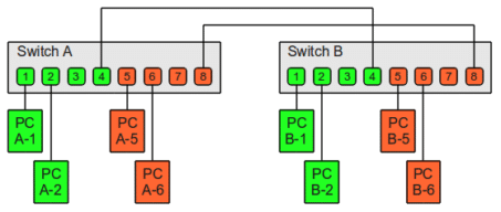
Two cables will be required for connecting both VLANs.
- One cable from Switch A Port 4 to Switch B Port 4 for VLAN 1 – Green
- One from Switch A Port 8 to Switch B Port 8 for VLAN 2 – Orange
Connection of both VLANs to the physical switch and since it is port-based, one cable per VLAN is required. Additionally, the PC’s can only see their VLAN and the other PC on the same one. Connection to infrastructure would use one port per VLAN, configured as shown below. For VLAN 1 either port A-3 or B-3 could be used to connect and only one should be to avoid a route loop. Same applies for VLAN 2 where either A-7 or B-7 could be used but not both, so again two cables total or one per VLAN. If this seems like a wiring nightmare it is which is why port based is used only where the interconnecting devices cannot understand VLAN ID’s encapsulated into the internet frame called tagging.
Tagged VLANs

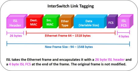
Structure of an Ethernet Frame

Structure of a VLAN Tag
A tag has two primary fields:
Tag protocol identifier or TPIDTag Control Information or TCI.
TPID is a 16-bit or 2-byte field set to a value of 0x8100 to identify the frame as an IEEE 802.1Q-tagged frame. This field is located at the same position as the EtherType/length field in untagged frames, and is thus used to distinguish the frame from untagged frames. A device unable to understand a 802.1q tagged frame would likely drop it as exceeding MTU size.
TCI is also 16-bit or 2-byte in length but has three subcomponents.
Priority code point (PCP) is a 3-bit field which refers to the IEEE 802.1p class of service and is how Quality of Service (Qos) is implemented.
Drop eligible indicator (DEI): a 1-bit field and may be used separately or in conjunction with PCP to indicate frames eligible to be dropped in the presence of congestion requiring frame drops.
VLAN identifier (VID) is a 12-bit field specifying the VLAN to which the frame belongs. The hexadecimal values of 0x000 and 0xFFF are reserved. All other values may be used as VLAN identifiers, allowing up to 4,094 VLANs. The reserved value 0x000 indicates that the frame does not carry a VLAN ID; in this case, the 802.1Q tag specifies only a priority and is referred to as a priority tag. On bridges, VID 0x001 (the default VLAN ID) is often reserved for a management VLAN but the management VLAN should be changed to a non-default ID. The VID value 0xFFF is reserved for implementation use; it must not be configured or transmitted. 0xFFF can be used to indicate a wildcard match in management operations or filtering database entries.


